-
EngIneerIng a better tomorrow
-

PartnerIng from concept to constructIon
-
Our excellence, your advantage
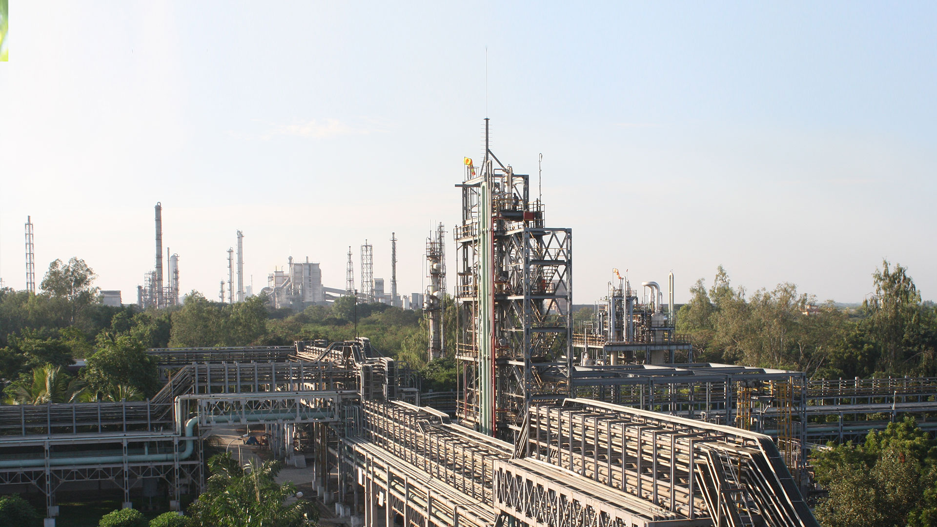
Technologies
In our decades of experience, we have catered to the major sectors of the process industry. Owing to the proprietary technology & know how, we have a strong presence in the chemical and specialty chemical sector.
IBI Chematur’s bio ethanol process is the continuous, proprietary BIOSTIL® 2000 process which can be used to convert sugar or starch based...
Acetaldehyde is produced by catalytic air oxidation in gas phase using silver catalyst.
The ethanol is taken to the acetic acid plant and is first converted to acetaldehyde, thereafter to acetic acid.
Engineering industry is the backbone of Industrial and Economic growth. The ambitious industrialization policy of the Indian Government...
Hydrogen Peroxide is an environmentally friendly chemical. Our production technology is based on the well known anthraquinone process...
Design & Engineering
Services
We undertake complete spectrum of activities from feasibility study, pre project planning, basic & detailed design followed by EPCM services for the entire lifecycle of the project; till commissioning; to meet a wide variety of client’s needs and stringent requirements covering major industries and sectors.
We typically undertake following Engineering Services for Greenfield, Brownfield, Revamp & modification, relocation & refurbishment projects in India & overseas.

IBIC qualified engineers analyse the strengths and weaknesses of the proposed project and provide options to achieve best technical solution with better profitability.
Allocation of versatile and well-experienced engineers to provide best in class solutions for project development.
Multi-discipline engineering resources, experienced and competent in developing Conceptual and Feasibility studies into a Front End Engineering and Design (FEED) package.
IBIC has a robust multi-disciplinary engineering team inn house with proven track record of delivering more than 100+ domestic & few global assignments successfully.
Vendor pre-qualification...
Finalise QA plan with contractor....
Expertise across sectors


Growth Is an ongoIng process
40+
years of profIcIency
120+
Projects executed
Major clients across geographIes